Pictures:
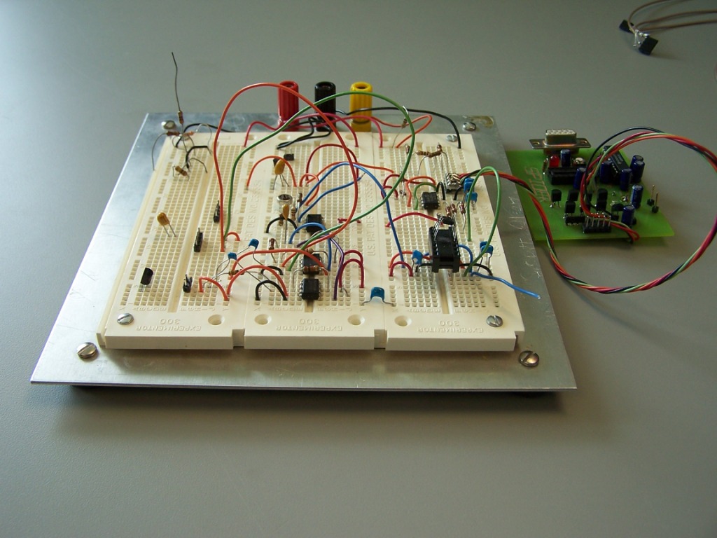
My first breadboarded EEG hardware. The basic design was INA114 inst-amp, TLC1078 op-amp, MAX7401 filter, PIC12F675, RS232 interface, PC running LabVIEW. Single 5.0 volt supply, with a TLE2426 "rail splitter" driving a 2.5v VGND. Another TLC1078 is used for a DRL (driven right leg) circuit. It is basically a simplified ModularEEG system with NO input protection, op-amp filter replaced with MAXIM filter, and Atmel processor replaced by a PIC. In the picture, the green board on the right has a MAX232 RS232 interface on it. Unit draws 14 mA with RS232 interface, 5 mA without. With this hardware I measured these ECG signals on my chest. On the blue trace (marked ECG G10) the instrumentation amp (inst-amp) had a gain of 10, and my system had a gain of 1000 (ECG mode). On the red trace (marked ECG G100) the inst-amp had a gain of 100, and my system had a gain of 10000 (EEG mode). In EEG mode my signals clip at 175uV, caused by non rail-to-rail output of the TLC1078. I have since replaced the TLC1078 with an AD8605 to remedy this. In EEG mode it had more 60 Hz noise which was improved with a better layout and gain line up.
My application software is written in LabVIEW. Here is a snapshot of the panel It reads in one or two channels of data and does an FFT. The PIC software takes commands from a PC via RS232, and sends 10 bit A/D samples to the PC. The PIC has a 4 channel A/D, I use 3 of them. PIC is configurable through RS232 commands for variable sample rate, variable calibration output frequency, which A/D channels to read, what to use as a reference voltage (5v supply or one of the A/D inputs). I use a software UART at 9600 baud, so I only have time to send two A/D channels at 256 Hz. (3 bytes for 2 10bit samples, sent ModEEG -p3 like). This lets me get away with using the PIC's internal 4MHz oscillator (look Mom, no crystal!). My target was something with very low part count (something I can easily breadboard), very low cost (my cost so far has been a $10 jar of Ten20 EEG paste!), and performance on par with similar home units.
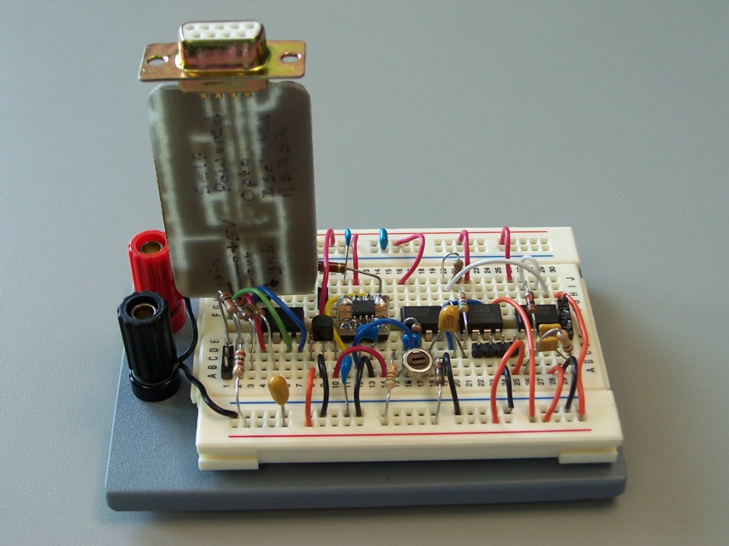
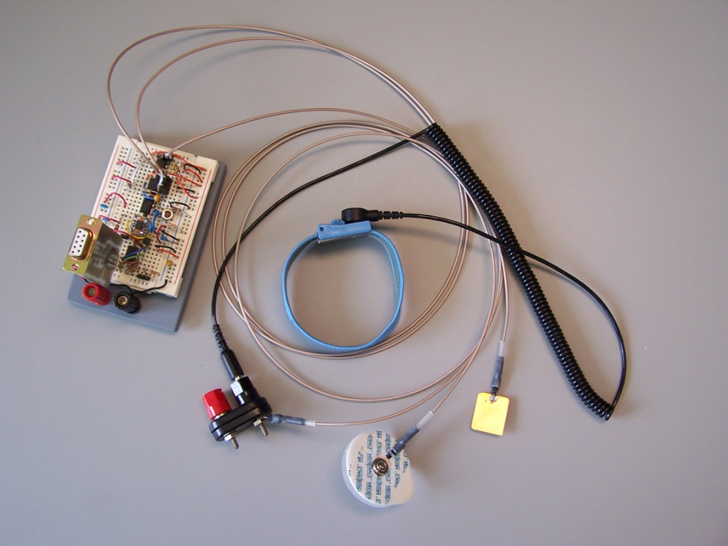
Here is a cleaned up breadboard. This less sprawling version has less 60 Hz noise (no surprise). Here is a picture with electrodes attached. The static wrist strap I used for my DRL. I used two of the white round Meditrace electrodes to take the ECG data I showed previously. The gold plate is an unfinished homemade EEG electrode. The PCB sticking out of the breadboard in an opto-isolated RS232 interface. Here is two seconds of EEG data with an FFT. You can see some 60 Hz noise (this is actually quite low, which is good), and some brain activity around 10 Hz.
Here is the EEG amplifier and microprocessor. The schematic shows a TL062 for the DRL op-amp, but my breadboard still has a TLC1078. Here is a schematic of my opto-isolated RS232 interface. It may not be bullet proof, but I've used it with one laptop and two desktop PCs at 9600 baud. It derives power from the RS232 lines. I only use it half duplex. I based the RS232 interface design on this one, by M Asim Khan, but I removed the LEDs and the buffers (among other things). A PIC12F675 running RS232 loopback code with this interface draws 0.8 mA sending 0x00 and 1.4 mA sending 0xFF (or vice versa, I forget). Here is a parts list with prices.
My planned to do list:
Prices of various parts taken off of the web sites of Digikey and Futurlec
(I've sampled all my semiconductors, so they haven't cost me anything)


If you wanted to build my EEG system:

------------------------------------------------
Analog section
--------------
INA114    $7.90 Futurlec
AD8605    $1.68 Digikey
MAX7401   $2.65 Digikey
TL062     $0.25 Futurlec
------------------------------------------------
Digital section
---------------
PIC12f675 $1.90 @Futurlec, $1.93 @Digikey
78L05     $0.20 Futurlec
TLE2426   $1.30 Digikey
PC817     $0.15 Futurlec (need 2)
DSUBPCF9  $0.55 Futurlec
4xAA Battery Holder:  $0.30 Futurlec
------------------------------------------------
various resistors and capacitors (price unknown)
------------------------------------------------


==================================================


Various parts that I have priced:

Instrumentation Amps
INA114      7.90 Futurlec, 8.40 Digikey (5.25/1000)
INA128U     9.40 Digikey
INA128UA    5.80 Digikey
LT1168      3.70/1000 (Linear's listed price)
AD8553      2.26/250, 1.64/3000 Digikey

Op Amps
TL062       0.25 Futurlec
TLC277      1.78 Digikey
OPA277U     2.03 Digikey
AD8605      1.68 Digikey

Filters
MAX296      4.43 Digikey
MAX7401     1.98 in 1k quantities, $2.65 Digikey

Power supply / Voltage reference
78L05       0.20 Futurlec
TL431       0.35 Futurlec
TLE2426CLP  1.30 Digikey

Digital stuff
PIC12f675   1.90 Futurlec, 1.93 Digikey
MAX232N     1.50 Futurlec, 0.90 Digikey
MAX232DR     .85 Futurlec

Hardware
4xAA Battery Holder  $0.30 Futurlec
DSUBPCF9             $0.55 Futurlec


;**********************************************************************************
; A/D to RS232 for PIC12F675
; Scott Olson, 03/07/2007
;
; RS232, GP3 input (Rx), GP4 output (Tx).  Analog inputs on AN0-AN2 (AN1=Vref)
; GP5 is a calibration output, it outputs a square wave of programable frequency
;
; Sends data as two's complement numbers, lsb first.
; 10 bit A/D values of 0-1023 are mapped to 0xFE00-0x01FF
; This is compatible with the "1 Channel Raw Data" Device in Chris Veigl's Brainbay
; Joerg Hansmann used this format in some early EEG archives
;
; Intitialized with 256 Hz sampling frequency (3906 usec delay)
; Cal output at 256/2/8 = 16 Hz
;
;**********************************************************************************

 list p=12f675           ; list directive to define processor
 #include <p12f675.inc> ; processor specific variable definitions
 errorlevel -302         ; suppress message 302 from list file

 __CONFIG   _CP_OFF & _CPD_OFF & _BODEN_OFF & _MCLRE_OFF & _WDT_OFF & _PWRTE_ON & _INTRC_OSC_NOCLKOUT

; Define variables

; Timer count. 65536-(time in usec) - instruction overhead (8) => 65528-time
Tmsb    equ     0xf0    ; count=3906 (3906.25 usec -> 256 Hz, so I'm off a little)
Tlsb    equ     0xb6
CalC    equ     D'08'   ; initialize Calibration count to 8 (equates to 16 Hz, 256Hz/2/8)

; Define digital GPIO port pins
RX      equ     3       ; Receive Pin (GP3)
TX      equ     4       ; Transmit Pin (GP4)
CAL     equ     5       ; calibration output (GP5)
TRISp   equ B'001111'   ; 0 is output, 1 is input

; this is for 9600 baud with 4 MHz clock
BAUD_1  equ     D'31'   ; 11+3X = CLKOUT/Baud, 31 (66 for 4800)
BAUD_X  equ     D'29'   ; 16+3X = CLKOUT/Baud, 29 (64 for 4800)

BAUD_4  equ     D'39'   ; 13+3X = 1.25*CLKOUT/Baud, 39 (82 for 4800)
BAUD_Y  equ     D'30'   ; 14+3X = CLKOUT/Baud, 30 (65 for 4800)

        CBLOCK  0x20
; these 4 items are for RS232 code
TxReg                  ; data to be transmitted
RxReg                  ; Data received
Count                  ; Counter for #of Bits Transmitted
DlyCnt

ADflag
c_msb
c_lsb
RampH                  ; ramp counter
RampL
Tout1                  ; These registers are from other code, only Tout3 is used here
Tout2                  ;    10 bit A/D 0-1023 maps to 0xFE00-0x01FF
Tout3                  ;    Tout3 is used to store msb
CalCnt                 ; counter for calibration output
CalN                   ; count value for Cal counter

   ENDC

      ORG    0x3ff            ; Internal RC oscillator callibration value
RCosc retlw  0x80             ; Device ID 0FC3, 0x3460

TB    MACRO  char             ; macro to transmit a byte
      movlw  char
      call   TxByte
      ENDM
;**********************************************************************

      ORG    0x000            ; processor reset vector
      goto   Init             ; go to beginning of program

      ORG    0x004
      goto   TimerInt

; these first 4 instructions are not required if the internal oscillator is not used
Init  bsf    STATUS, RP0      ; Bank 1
      call   RCosc            ; retrieve factory calibration value
      movwf  OSCCAL           ; update register with factory cal value
      bcf    STATUS, RP0      ; Bank 0

; Initialize ports
      movlw  B'010000'       ; Initial value of ports
      movwf  GPIO
      movlw  0x07             ; set GP<2:0> comparator off
      movwf  CMCON
      bsf    STATUS, RP0      ; Bank 1
      movlw  B'01010111'      ; 16*Tosc, analog inputs on AN2:AN0 , digital GP3
      movwf  ANSEL
      movlw  TRISp            ; see port definition equates
      movwf  TRISIO
      bcf    STATUS, RP0      ; Bank 0
      movlw  B'11000001'      ; right justified, ref=Vref pin, chan AN0, turn on A/D
      movwf  ADCON0

; setup Timer1 and A/D
      movlw  Tmsb             ; initialize timer count registers
      movwf  c_msb
      movwf  TMR1H
      movlw  Tlsb
      movwf  c_lsb
      movwf  TMR1L
      movlw  CalC             ; initialize calibration count
      movwf  CalN
      movwf  CalCnt

      clrf   PIR1             ; clear interupt flags
      movlw  B'00000001'      ; timer1 on, 1:1 prescaler
      movwf  T1CON
      bsf    STATUS, RP0      ; Bank 1
      movlw  B'00000001'      ; Enable Timer1 interupt
      movwf  PIE1
      bcf    STATUS, RP0      ; Bank 0
      movlw  B'11000000'      ; Enable interupts
      movwf  INTCON

      bcf    ADflag, 0        ; clear flag, ADstart
      bsf    ADflag, 1        ; 0=stop, 1=go
      bcf    ADflag, 2        ; 0=AD->RS232, 1=ramp->RS232
      bcf    ADflag, 3        ; 0=1 channel, 1=2 channels (always channels 0 and 2)
                              ; *** 2 channels not valid in this code
      bsf    ADflag, 4        ; cal output on
      bsf    Tout3, 7         ; set pilot bits  *** this is not needed for
      bcf    Tout3, 3         ;                 *** for raw format

Main  btfsc  ADflag, 0        ; wait for flag to start A/D data
      goto   startAD
      btfss  GPIO, RX         ; check for a RS232 Start Bit
      goto   GetCmd
      goto   Main             ; loop if nothing there

;*****************************************************************
; all commands start with an ASCII '0' (one long low), use this to resync to next start bit
GetCmd
      bcf    T1CON, TMR1ON    ; stop timer
wRE   btfss  GPIO, RX         ; wait for next rising edge
      goto   wRE
      call   RxByte           ; command is now in RxReg

      movlw  D'65'            ; "A" is A/D->232
      subwf  RxReg, w         ; A<n> specifies A/D channels: A0, A1, A2 or A3. A3 means A0 & A2
      btfsc  STATUS, Z
      goto   AD
      movlw  D'67'            ; "C" is Calibrate
      subwf  RxReg, w         ; C<n> specifies calibration output count which is A/D sample count
      btfsc  STATUS, Z        ; times n. C0 turns off cal output.
      goto   cal
      movlw  D'71'            ; "G" is go
      subwf  RxReg, w         ; Starts RS232 output
      btfsc  STATUS, Z
      goto   go
      movlw  D'78'            ; "N" is Counter
      subwf  RxReg, w         ; N<msb><lsb> specifies the A/D sample count. The actual number of the
      btfsc  STATUS, Z        ; count is in milliseconds is 65528-N. Also effects cal output frequency
      goto   counter
      movlw  D'80'            ; "P" is Prescaler
      subwf  RxReg, w         ; A/D sample count (and cal frequency) is also a function of the prescaler
      btfsc  STATUS, Z        ; Use this only to get really slow sampling (non EEG applications)
      goto   prescaler
      movlw  D'83'            ; "S" means stop
      subwf  RxReg, w         ; Stops RS232 output
      btfsc  STATUS, Z
      goto   stop
      movlw  D'82'            ; "R" is ramp->RS232
      subwf  RxReg, w         ; Send ramp signals instead of A/D samples
      btfsc  STATUS, Z        ; (an artifact from early software debug)
      goto   ramp
      movlw  D'86'            ; "V" is Vref (also Version information)
      subwf  RxReg, w         ; V0 = use Vref pin input (A1) as A/D reference voltage
      btfsc  STATUS, Z        ; V1 = use Vdd as A/D reference voltage
      goto   vref             ; V2 = use Vref, also send software version info, and stop
                              ; V3 = use Vdd,  also send software version info, and stop

      TB     "B"              ; Whoops! we didn't see a valid command. Say so and stop.
      TB     "a"
      TB     "d"
      TB     " "
      TB     "C"
      TB     "m"
      TB     "d"
      goto   stop             ; not a command

;*****************************************************************
; Command functions
AD    bcf    ADflag, 3        ; clear number of channels flag (1 channel)
      bcf    ADflag, 2        ; "A" is A/D channel where
      call   RxByte           ;     0=chan0, 1=chan1, 2=chan2, 3=chan0 and chan2
      bcf    ADCON0, 2        ; clear lsb of A/D selected channel
      bcf    ADCON0, 3        ; clear msb of A/D selected channel
      btfsc  RxReg, 1
      goto   tor2             ; msbit (of 2 bits) was a 1, which means either chan2 or 2-channels
zor1  btfsc  RxReg, 0         ; channel 0 or 1
      bsf    ADCON0, 2        ; channel 1
      goto   resume
tor2  bsf    ADCON0, 3        ; channel 2 or 0and2
      btfss  RxReg, 0
      goto   resume           ; channel 2
      bcf    ADCON0, 3        ; channels 0 and 2, reset for channel 0 first
      bsf    ADflag, 3        ; set 2 channel flag
      goto   resume

cal   call   RxByte
      movf   RxReg, w
      iorlw  0                ; is cal count a 0?
      btfss  STATUS, Z
      goto   scal             ; no, set cal counter
      bcf    ADflag, 4        ; turn off cal function
      goto   resume
scal  movwf  CalN             ; store new cal counter value
      bsf    ADflag, 4        ; turn on cal function
      goto   resume

go    bsf    ADflag, 1
      goto   resume

counter
      call   RxByte
      movf   RxReg, w
      movwf  c_msb
      call   RxByte
      movf   RxReg, w
      movwf  c_lsb
      goto   resume

prescaler
      call   RxByte
      movf   T1CON, w         ; get present register state
      andlw  B'11001111'      ; keep all but prescaler bits
      movwf  T1CON            ; put it back
      rlf    RxReg, f         ; align prescaler RS232 command with control reg position
      rlf    RxReg, f
      rlf    RxReg, f
      rlf    RxReg, f
      movf   RxReg, w         ; get number from RS232 buffer
      andlw  B'00110000'      ; mask off all but prescaler bits
      iorwf  T1CON, f         ; put new prescaler bits in control reg
      goto   resume

ramp  bsf    ADflag, 2
      goto   resume

stop  bcf    ADflag, 1
      goto   resume

vref  call   RxByte           ; use Vdd or Vref pin for A/D reference? (0=Vref pin, 1=Vdd)
      bcf    ADCON0, 6        ; to use Vdd
      btfss  RxReg, 0
      bsf    ADCON0, 6        ; to use Vref pin
      btfss  RxReg, 1         ; also send version info?
      goto   resume           ;   no, just resume
      TB     "p"
      TB     "i"
      TB     "c"
      TB     "A"
      TB     "D"
      TB     " "
      TB     "v"
      TB     "0"
      TB     "."
      TB     "0"
      TB     "1"
      TB     "d"
      goto   stop

resume
      bsf    T1CON, TMR1ON    ; start timer
      goto   Main

;*****************************************************************
; Start A/D conversion. First check if cal output should be toggled
startAD
      btfss  ADflag, 4        ; do we want a cal output?
      goto   AD7              ;   no, just do A/D [3] [number is how many cycles]
      decfsz CalCnt, f        ;   yes, decrement cal counter
      goto   AD5              ; don't do anything if count not complete [5]
      btfsc  GPIO, CAL        ; toggle cal output
      goto   Clo              ; cal output is high, make it go low
      nop
      bsf    GPIO, CAL        ; cal output is low, make it go high [7]
      movf   CalN, w          ; reset cal counter
      movwf  CalCnt
      goto   AD0              ; [10]
Clo   bcf    GPIO, CAL        ; [7]
      movf   CalN, w          ; reset cal counter
      movwf  CalCnt
      goto   AD0              ; [10]

AD7   nop                     ; these nops are so that the timing is the same
AD6   nop                     ;    no matter what path it took to get to AD0
AD5   nop
AD4   nop
AD3   nop
AD2   nop
AD1   nop
AD0   bcf    ADflag, 0        ; clear flag
      bcf    PIR1, 6
      bsf    ADCON0, 1        ; start A/D
wAD   btfss  PIR1, 6          ; wait for A/D completion
      goto   wAD

      btfss  ADflag, 1        ; go/stop flag
      goto   Main
      btfss  ADflag, 2        ; AD/Ramp flag
      goto   sendAD
      goto   sendINC

;*****************************************************************
; this is legacy stuff to test RS232 hardware and protocol
sendINC
      incf   RampL, f         ; increment 16 bit counter
      btfsc  STATUS, Z        ;   (only care about 10 bits)
      incf   RampH, f
      movf   RampL, w         ; send out lsb
      call   TxByte           ; 1st packet byte
      btfss  GPIO, RX         ; check for a RS232 Start Bit (incoming command?)
      goto   GetCmd
      movf   RampH, w         ; get msb
      andlw  B'00000011'      ; mask off top 6 bits
      movwf  Tout3
      decf   Tout3, f         ; format for 1 raw
      decf   Tout3, f
srT3  movf   Tout3, w
      call   TxByte           ; send last byte in packet
      goto   Main

;*****************************************************************
sendAD
      movf   ADRESH, w        ; get msb
      andlw  B'00000011'      ; mask off top 6 bits
      movwf  Tout3            ; save
      decf   Tout3, f         ; format for 1 raw
      decf   Tout3, f
      bsf    STATUS, RP0      ; Bank 1 (i hate banks)
      movf   ADRESL, w        ; get lsb
      bcf    STATUS, RP0      ; Bank 0 (i still hate banks)
      call   TxByte           ; send lsb
      btfss  GPIO, RX         ; check for a RS232 Start Bit (incoming command?)
      goto   GetCmd
sT3   movf   Tout3, w         ; send last packet byte (formated msb)
      call   TxByte           ; send it
      goto   Main

;*****************************************************************
; Interupt service routine
TimerInt
      bcf    T1CON, TMR1ON    ; stop timer

      movf   c_msb, w         ; initialize timer
      movwf  TMR1H
      movf   c_lsb, w
      movwf  TMR1L

      bsf    ADflag, 0        ; set A/D flag to tell main routine to do a converstion

      bcf    PIR1, TMR1IF     ; clear interupt flag
      bsf    T1CON, TMR1ON    ; start timer

      retfie                  ; return from interupt

;*****************************************************************
; Byte is returned in RxReg
RxByte: btfsc   GPIO, RX      ; wait for a Start Bit
        goto    RxByte

Rcvr:   call    Delay4        ; delay for 104+104/4
        movlw   8             ; 8 Data bits
        movwf   Count
R_next: bcf     STATUS,C
        rrf     RxReg,f
        btfsc   GPIO, RX
        bsf     RxReg,7
        call    DelayY
        decfsz  Count,f
        goto    R_next
        return

;**********************************************************
; put byte for transmission in w
TxByte: movwf   TxReg
Xmtr:   movlw   8             ; initialize bit counter
        movwf   Count
        bcf     GPIO,TX       ; Send Start Bit
        call    Delay1

X_next: rrf     TxReg, f
        btfsc   STATUS, C
        goto    Tx1
Tx0     nop                   ; see that bit is send at same time whether 0 or 1
        bcf     GPIO, TX      ; send a 0
        goto    D1b
Tx1     bsf     GPIO, TX      ; send a 1
        nop                   ; see that timing is the same as that of a 0
        nop
D1b     call    DelayX
        decfsz  Count, f
        goto    X_next
        bsf     GPIO, TX      ; Send Stop Bit
        call    Delay1        ; close enough (maybe 1 cycle off)
        retlw   0

DelayY: movlw   BAUD_Y
        goto    save
DelayX: movlw   BAUD_X
        goto    save
Delay4: movlw   BAUD_4
        goto    save
Delay1: movlw   BAUD_1
        goto    save
save:   movwf   DlyCnt
redo_1: decfsz  DlyCnt,f
        goto    redo_1
        retlw   0

        END
OLD CODE
;**********************************************************************************
; A/D to RS232 for PIC12F675
; Scott Olson, 7/10/2006
;
; RS232, GP3 input (Rx), GP4 output (Tx).  Analog inputs on AN0-AN2 (AN1=Vref)
; GP5 is a calibration output, it outputs a square wave of programable frequency
;
; packets are ModularEEG -p3 like.
; -p3 only has even number of channels, and it has a header. Mine has one or two channels and no header
;
; One channel packet (AN0,AN1 or AN2)     Two channel packet (always AN0 and AN2)
; 0aaaaaaa                                0aaaaaaa
; 1aaa0000                                0bbbbbbb
; repeat                                  1aaa0bbb
;                                         repeat
;
;**********************************************************************************

 list p=12f675           ; list directive to define processor
 #include <p12f675.inc> ; processor specific variable definitions
 errorlevel -302         ; suppress message 302 from list file

 __CONFIG   _CP_OFF & _CPD_OFF & _BODEN_OFF & _MCLRE_OFF & _WDT_OFF & _PWRTE_ON & _INTRC_OSC_NOCLKOUT

; Define variables

; Timer count. 65536-(time in usec) - instruction overhead (8) => 65528-time
Tmsb    equ     0xf0    ; count=4000 (4 msec -> 250 Hz)
Tlsb    equ     0x58
CalC    equ     D'10'   ; initialize Calibration count to 10 (equates to 12.5 Hz, 250Hz/2/10)

; Define digital GPIO port pins
RX      equ     3       ; Receive Pin (GP3)
TX      equ     4       ; Transmit Pin (GP4)
CAL     equ     5       ; calibration output (GP5)
TRISp   equ B'001111'   ; 0 is output, 1 is input

; this is for 9600 baud with 4 MHz clock
BAUD_1  equ     D'31'   ; 11+3X = CLKOUT/Baud, 31 (66 for 4800)
BAUD_X  equ     D'29'   ; 16+3X = CLKOUT/Baud, 29 (64 for 4800)

BAUD_4  equ     D'39'   ; 13+3X = 1.25*CLKOUT/Baud, 39 (82 for 4800)
BAUD_Y  equ     D'30'   ; 14+3X = CLKOUT/Baud, 30 (65 for 4800)

        CBLOCK  0x20
; these 4 items are for RS232 code
TxReg                  ; data to be transmitted
RxReg                  ; Data received
Count                  ; Counter for #of Bits Transmitted
DlyCnt

ADflag
c_msb
c_lsb
RampH
RampL
Tout1                  ;  first byte in packet 0aaaaaaa : 7 lsb of 1st channel
Tout2                  ; second byte in packet 0bbbbbbb : (or 1aaa00000 if only one channel)
Tout3                  ;  third byte in packet 1aaa0bbb : 3 msb of both channels
CalCnt                 ; counter for calibration output
CalN                   ; count value for Cal counter
   ENDC

      ORG    0x3ff            ; Internal RC oscillator callibration value
RCosc retlw  0x80             ; Device ID 0FC3, 0x3460

TB    MACRO  char             ; macro to transmit a byte
      movlw  char
      call   TxByte
      ENDM
;**********************************************************************

      ORG    0x000            ; processor reset vector
      goto   Init             ; go to beginning of program

      ORG    0x004
      goto   TimerInt

; these first 4 instructions are not required if the internal oscillator is not used
Init  bsf    STATUS, RP0      ; Bank 1
      call   RCosc            ; retrieve factory calibration value
      movwf  OSCCAL           ; update register with factory cal value
      bcf    STATUS, RP0      ; Bank 0

; Initialize ports
      movlw  B'010000'       ; Initial value of ports
      movwf  GPIO
      movlw  0x07             ; set GP<2:0> comparator off
      movwf  CMCON
      bsf    STATUS, RP0      ; Bank 1
      movlw  B'01010111'      ; 16*Tosc, analog inputs on AN2:AN0 , digital GP3
      movwf  ANSEL
      movlw  TRISp            ; see port definition equates
      movwf  TRISIO
      bcf    STATUS, RP0      ; Bank 0
      movlw  B'11000001'      ; right justified, ref=Vref pin, chan AN0, turn on A/D
      movwf  ADCON0

; setup Timer1 and A/D
      movlw  Tmsb             ; initialize timer count registers
      movwf  c_msb
      movwf  TMR1H
      movlw  Tlsb
      movwf  c_lsb
      movwf  TMR1L
      movlw  CalC             ; initialize calibration count
      movwf  CalN
      movwf  CalCnt

      clrf   PIR1             ; clear interupt flags
      movlw  B'00000001'      ; timer1 on, 1:1 prescaler
      movwf  T1CON
      bsf    STATUS, RP0      ; Bank 1
      movlw  B'00000001'      ; Enable Timer1 interupt
      movwf  PIE1
      bcf    STATUS, RP0      ; Bank 0
      movlw  B'11000000'      ; Enable interupts
      movwf  INTCON

      bcf    ADflag, 0        ; clear flag, ADstart
      bsf    ADflag, 1        ; 0=stop, 1=go
      bcf    ADflag, 2        ; 0=AD->RS232, 1=ramp->RS232
      bcf    ADflag, 3        ; 0=1 channel, 1=2 channels (always channels 0 and 2)
      bcf    ADflag, 4        ; cal output off
      bsf    Tout3, 7         ; set pilot bits
      bcf    Tout3, 3

Main  btfsc  ADflag, 0        ; wait for flag to start A/D data
      goto   startAD
      btfss  GPIO, RX         ; check for a RS232 Start Bit
      goto   GetCmd
      goto   Main             ; loop if nothing there

;*****************************************************************
; all commands start with an ASCII '0' (one long low), use this to resync to next start bit
GetCmd
      bcf    T1CON, TMR1ON    ; stop timer
wRE   btfss  GPIO, RX         ; wait for next rising edge
      goto   wRE
      call   RxByte           ; command is now in RxReg

      movlw  D'65'            ; "A" is A/D->232
      subwf  RxReg, w         ; A<n> specifies A/D channels: A0, A1, A2 or A3. A3 means A0 & A2
      btfsc  STATUS, Z
      goto   AD
      movlw  D'67'            ; "C" is Calibrate
      subwf  RxReg, w         ; C<n> specifies calibration output count which is A/D sample count
      btfsc  STATUS, Z        ; times n. C0 turns off cal output.
      goto   cal
      movlw  D'71'            ; "G" is go
      subwf  RxReg, w         ; Starts RS232 output
      btfsc  STATUS, Z
      goto   go
      movlw  D'78'            ; "N" is Counter
      subwf  RxReg, w         ; N<msb><lsb> specifies the A/D sample count. The actual number of the
      btfsc  STATUS, Z        ; count is in milliseconds is 65528-N. Also effects cal output frequency
      goto   counter
      movlw  D'80'            ; "P" is Prescaler
      subwf  RxReg, w         ; A/D sample count (and cal frequency) is also a function of the prescaler
      btfsc  STATUS, Z        ; Use this only to get really slow sampling (non EEG applications)
      goto   prescaler
      movlw  D'83'            ; "S" means stop
      subwf  RxReg, w         ; Stops RS232 output
      btfsc  STATUS, Z
      goto   stop
      movlw  D'82'            ; "R" is ramp->RS232
      subwf  RxReg, w         ; Send ramp signals instead of A/D samples
      btfsc  STATUS, Z        ; (an artifact from early software debug)
      goto   ramp
      movlw  D'86'            ; "V" is Vref (also Version information)
      subwf  RxReg, w         ; V0 = use Vref pin input (A1) as A/D reference voltage
      btfsc  STATUS, Z        ; V1 = use Vdd as A/D reference voltage
      goto   vref             ; V2 = use Vref, also send software version info, and stop
                              ; V3 = use Vdd,  also send software version info, and stop

      TB     "B"              ; Whoops! we didn't see a valid command. Say so and stop.
      TB     "a"
      TB     "d"
      TB     " "
      TB     "C"
      TB     "m"
      TB     "d"
      goto   stop             ; not a command

;*****************************************************************
; Command functions
AD    bcf    ADflag, 3        ; clear number of channels flag (1 channel)
      bcf    ADflag, 2        ; "A" is A/D channel where
      call   RxByte           ;     0=chan0, 1=chan1, 2=chan2, 3=chan0 and chan2
      bcf    ADCON0, 2        ; clear lsb of A/D selected channel
      bcf    ADCON0, 3        ; clear msb of A/D selected channel
      btfsc  RxReg, 1
      goto   tor2             ; msbit (of 2 bits) was a 1, which means either chan2 or 2-channels
zor1  btfsc  RxReg, 0         ; channel 0 or 1
      bsf    ADCON0, 2        ; channel 1
      goto   resume
tor2  bsf    ADCON0, 3        ; channel 2 or 0and2
      btfss  RxReg, 0
      goto   resume           ; channel 2
      bcf    ADCON0, 3        ; channels 0 and 2, reset for channel 0 first
      bsf    ADflag, 3        ; set 2 channel flag
      goto   resume

cal   call   RxByte
      movf   RxReg, w
      iorlw  0                ; is cal count a 0?
      btfss  STATUS, Z
      goto   scal             ; no, set cal counter
      bcf    ADflag, 4        ; turn off cal function
      goto   resume
scal  movwf  CalN             ; store new cal counter value
      bsf    ADflag, 4        ; turn on cal function
      goto   resume

go    bsf    ADflag, 1
      goto   resume

counter
      call   RxByte
      movf   RxReg, w
      movwf  c_msb
      call   RxByte
      movf   RxReg, w
      movwf  c_lsb
      goto   resume

prescaler
      call   RxByte
      movf   T1CON, w         ; get present register state
      andlw  B'11001111'      ; keep all but prescaler bits
      movwf  T1CON            ; put it back
      rlf    RxReg, f         ; align prescaler RS232 command with control reg position
      rlf    RxReg, f
      rlf    RxReg, f
      rlf    RxReg, f
      movf   RxReg, w         ; get number from RS232 buffer
      andlw  B'00110000'      ; mask off all but prescaler bits
      iorwf  T1CON, f         ; put new prescaler bits in control reg
      goto   resume

ramp  bsf    ADflag, 2
      goto   resume

stop  bcf    ADflag, 1
      goto   resume

vref  call   RxByte           ; use Vdd or Vref pin for A/D reference? (0=Vref pin, 1=Vdd)
      bcf    ADCON0, 6        ; to use Vdd
      btfss  RxReg, 0
      bsf    ADCON0, 6        ; to use Vref pin
      btfss  RxReg, 1         ; also send version info?
      goto   resume           ;   no, just resume
      TB     "p"
      TB     "i"
      TB     "c"
      TB     "A"
      TB     "D"
      TB     " "
      TB     "v"
      TB     "0"
      TB     "."
      TB     "0"
      TB     "1"
      TB     "c"
      goto   stop

resume
      bsf    T1CON, TMR1ON    ; start timer
      goto   Main

;*****************************************************************
; Start A/D conversion. First check if cal output should be toggled
startAD
      btfss  ADflag, 4        ; do we want a cal output?
      goto   AD7              ;   no, just do A/D [3] [number is how many cycles]
      decfsz CalCnt, f        ;   yes, decrement cal counter
      goto   AD5              ; don't do anything if count not complete [5]
      btfsc  GPIO, CAL        ; toggle cal output
      goto   Clo              ; cal output is high, make it go low
      nop
      bsf    GPIO, CAL        ; cal output is low, make it go high [7]
      movf   CalN, w          ; reset cal counter
      movwf  CalCnt
      goto   AD0              ; [10]
Clo   bcf    GPIO, CAL        ; [7]
      movf   CalN, w          ; reset cal counter
      movwf  CalCnt
      goto   AD0              ; [10]

AD7   nop                     ; these nops are so that the timing is the same
AD6   nop                     ;    no matter what path it took to get to AD0
AD5   nop
AD4   nop
AD3   nop
AD2   nop
AD1   nop
AD0   bcf    ADflag, 0        ; clear flag
      bcf    PIR1, 6
      bsf    ADCON0, 1        ; start A/D
wAD   btfss  PIR1, 6          ; wait for A/D completion
      goto   wAD

      btfss  ADflag, 1        ; go/stop flag
      goto   Main
      btfss  ADflag, 2        ; AD/Ramp flag
      goto   sendAD
      goto   sendINC

;*****************************************************************
; this is legacy stuff to test RS232 hardware and protocol
sendINC
      incf   RampL, f         ; increment 16 bit counter
      btfsc  STATUS, Z
      incf   RampH, f
      movf   RampL, w         ; send out lsb
      movwf  Tout1
      bcf    Tout1, 7
      movf   Tout1, w
      call   TxByte           ; 1st packet byte
      btfss  GPIO, RX         ; check for a RS232 Start Bit (incoming command?)
      goto   GetCmd
      clrf   Tout3            ; format last byte
      bsf    Tout3, 7
      btfsc  RampL, 7
      bsf    Tout3, 4
      btfsc  RampH, 0
      bsf    Tout3, 5
      btfsc  RampH, 1
      bsf    Tout3, 6
      btfss  ADflag, 3        ; are we in 2 channel mode?
      goto   srT3             ;    if not, just send last byte
      movf   RampL, w         ; just send RampL <7:0>
      movwf  Tout2
      comf   Tout2, f         ; compliment it to make it more interesting
      btfsc  Tout2, 7
      bsf    Tout3, 0         ; do 7th bit
      bcf    Tout2, 7
      movf   Tout2, w
      call   TxByte           ; send 2nd byte in 3 byte packet
      btfss  GPIO, RX         ; check for a RS232 Start Bit (incoming command?)
      goto   GetCmd
srT3  movf   Tout3, w
      call   TxByte           ; send last byte in packet
      goto   Main

;*****************************************************************
sendAD
      movf   ADRESH, w        ; get msb
      movwf  Tout3
      swapf  Tout3, f         ; shift bits 4 to left
      bcf    STATUS, C
      rlf    Tout3, f
      bsf    STATUS, RP0      ; Bank 1 (i hate banks)
      movf   ADRESL, w        ; get lsb
      bcf    STATUS, RP0      ; Bank 0 (i still hate banks)
      movwf  Tout1
      btfsc  Tout1, 7         ; put bit 7 in Tout3 bit 4 (if zero, its already there)
      bsf    Tout3, 4
      bcf    Tout1, 7         ; make sure bit 7 of  Tout is clear
      bsf    Tout3, 7         ; set bit 7 of Tout3 (sync bit)
      movf   Tout1, w         ; get 1st byte to send
      call   TxByte           ; send 1st channel lsb <6:0>
      btfss  GPIO, RX         ; check for a RS232 Start Bit (incoming command?)
      goto   GetCmd
      btfss  ADflag, 3        ; do we send 2 channels?
      goto   sT3              ;   no, jump to send Tout3
      bsf    ADCON0, 3        ; prepare for A/D on channel 2
                              ; at this point there needs to be a 10us setup time ?
                              ; but did we already get it from the TxByte time, or do
                              ; we need it after setting the channel mux?
      movlw  D'10'            ; for safety, I'll put in the delay
      movwf  DlyCnt
sud   decfsz DlyCnt, f
      goto   sud

      bcf    PIR1, 6          ; clear "A/D done" flag
      bsf    ADCON0, 1        ; start A/D
wAD2  btfss  PIR1, 6          ; wait for A/D completion
      goto   wAD2
      ; we have a second channel to send (2nd byte of 3 byte packet)
      btfsc  ADRESH, 1
      bsf    Tout3, 2         ; put bit 9 in place
      btfsc  ADRESH, 0
      bsf    Tout3, 1         ; put bit 8 in place
      bsf    STATUS, RP0      ; Bank 1 (i hate banks)
      movf   ADRESL, w        ; get lsb
      bcf    STATUS, RP0      ; Bank 0 (i still hate banks)
      movwf  Tout2
      btfsc  Tout2, 7
      bsf    Tout3, 0         ; put bit 7 in place
      bcf    Tout2, 7         ; make sure bit 7 is clear
      bcf    ADCON0, 3        ; prepare for A/D channel 0 on next round
      movf   Tout2, w
      call   TxByte           ; send second channel lsb <6:0>
      btfss  GPIO, RX         ; check for a RS232 Start Bit (incoming command?)
      goto   GetCmd
sT3   movf   Tout3, w         ; get last byte to send <1aaa0bbb>
      call   TxByte           ; send it
      goto   Main


;*****************************************************************
; Interupt service routine
TimerInt
      bcf    T1CON, TMR1ON    ; stop timer

      movf   c_msb, w         ; initialize timer
      movwf  TMR1H
      movf   c_lsb, w
      movwf  TMR1L

      bsf    ADflag, 0        ; set A/D flag to tell main routine to do a converstion

      bcf    PIR1, TMR1IF     ; clear interupt flag
      bsf    T1CON, TMR1ON    ; start timer

      retfie                  ; return from interupt

;*****************************************************************
; Byte is returned in RxReg
RxByte: btfsc   GPIO, RX      ; wait for a Start Bit
        goto    RxByte

Rcvr:   call    Delay4        ; delay for 104+104/4
        movlw   8             ; 8 Data bits
        movwf   Count
R_next: bcf     STATUS,C
        rrf     RxReg,f
        btfsc   GPIO, RX
        bsf     RxReg,7
        call    DelayY
        decfsz  Count,f
        goto    R_next
        return

;**********************************************************
; put byte for transmission in w
TxByte: movwf   TxReg
Xmtr:   movlw   8             ; initialize bit counter
        movwf   Count
        bcf     GPIO,TX       ; Send Start Bit
        call    Delay1

X_next: rrf     TxReg, f
        btfsc   STATUS, C
        goto    Tx1
Tx0     nop                   ; see that bit is send at same time whether 0 or 1
        bcf     GPIO, TX      ; send a 0
        goto    D1b
Tx1     bsf     GPIO, TX      ; send a 1
        nop                   ; see that timing is the same as that of a 0
        nop
D1b     call    DelayX
        decfsz  Count, f
        goto    X_next
        bsf     GPIO, TX      ; Send Stop Bit
        call    Delay1        ; close enough (maybe 1 cycle off)
        retlw   0

DelayY: movlw   BAUD_Y
        goto    save
DelayX: movlw   BAUD_X
        goto    save
Delay4: movlw   BAUD_4
        goto    save
Delay1: movlw   BAUD_1
        goto    save
save:   movwf   DlyCnt
redo_1: decfsz  DlyCnt,f
        goto    redo_1
        retlw   0

        END
1 yorum:
Hi,
im an egineering student and im developing a EEG system based on the OpenEEG project using LabVIEW to capture and process the signals.
Reading your article, i realize that you successfully captured the serial signals from the OpenEEG and aplied the FFT transform to it, and im wondering if you could help me with it.
Thank you
Gustavo gustux@gmail.com
Yorum Gönder