
Today I will show how to make digital bridge between Arduino and PC: control analog – digital converter and send measured data to PC. Windows application will be created using Visual C++ 2008 Express.
Voltmeter demo software is very simple, and here is a lot room for improvement, but I just wanted to show basics how to control com port and execute data exchange between PC and Arduino.
Communication between Arduino and PC:
- ADC measurement loop starts when PC sends 0xAC and 0x1y to Arduino. Where y is ADC channel number(0-2);
- Measurement stops after Arduino receives 0xAC and 0×00;
- In measurement loop with 50ms delay Arduino sends 0xAB 0xaa 0xbb, where aa and bb is higher and lower bytes of measurement result.
Arduino code
More about serial communication You could find at arduino.cc. Code is simple, the biggest part of it takes switch structure that takes action if data available at serial port buffer. If it’s so ADC conversion is started on selected channel, or stopped accordingly to received data.
After ADC conversion is finished there is 10 bit voltage value (0×0000-0×0400) in 16 bit variable (int). Serial (RS-232) protocol enables sending data in packets, where raw data can contain maximum 8 bits. It gives a need to split 16 bit variable in 2 parts of 8 bits. To get higher byte variable is shifted to right by 8 bits. To get lower byte variable is divided by 256 and remainder is taken.
    Serial.print(voltage>>8,BYTE);
    Serial.print(voltage%256,BYTE);
Full Arduino code:
//electronicsblog.net
//Arduino communication with PC via serial port.

int voltage=0;
int channel =0;
unsigned char incomingByte = 0;
boolean measure=false;

void setup() {

  Serial.begin(9600);
}

void loop() {

  if (measure) {

    voltage=analogRead(channel);
    Serial.print(0xAB,BYTE);
    Serial.print(voltage>>8,BYTE);
    Serial.print(voltage%256,BYTE);
    delay(50);

  }

  if (Serial.available() > 0) {
    delay(10);

    if(Serial.read()==0xAC) {
      incomingByte =Serial.read();

      switch (incomingByte) {

      case 0x10:
        measure=true;
        channel=0;
        break;

      case 0x11:
        measure=true;
        channel=1;
        break;

      case 0x12:
        measure=true;
        channel=2;
        break;

      case 0x00:
        measure=false;
        break;

      }

    }

  }

};
Visual C++
I assume, that You already have a basic knowledge of Windows forms programing in C++, if not when just Google, internet is full of examples for beginners.

First thing to do is add serial port resource from toolbar to area below form. Properties allows to change some important settings of serial port: port name, baud rate, databits. It’s more useful to add controls in application window to change these settings any time, without need to recompile program again. “Voltmeter demo” application have only one of these control and it’s dropdown list of available ports.

After retrieval of available serial port names list the first port is selected as default. Code for that trick:
array< String ^>^ serialPorts = nullptr;
serialPorts = serialPort1->GetPortNames();
this->comboBox1->Items->AddRange(serialPorts);
this->comboBox1->SelectedIndex=0;
Serial port in PC could be used only by one application at one time, so port must be opened before use, and closed after no longer needed. Simple commands for that:
serialPort1->Open();
serialPort1->Close();
Reading serial port. To do is properly, it’s necessary to use “received data” event (interrupt) . At serial port properties select events.

When double click “DataReceived” drop-down list.
Event’s function code is automatically generated:
private: System::Void serialPort1_DataReceived(System::Object^ sender, System::IO::Ports::SerialDataReceivedEventArgs^ e) {
}
Code from “Voltmeter demo”:
Where is a check to see if first byte arrived to serial port is 0xAB, if is it means, that other bytes carries voltage data. In other case blank reading is executed to clean serial port buffer.
private: System::Void serialPort1_DataReceived(System::Object^ sender, System::IO::Ports::SerialDataReceivedEventArgs^ e) {
unsigned char data0, data1;
if (serialPort1->ReadByte()==0xAB) {
data0=serialPort1->ReadByte();
data1=serialPort1->ReadByte();voltage=Math::Round((float(data0*256+data1)/1024*5.00),2);data_count++;}
serialPort1->ReadByte();
}
Sending data/writing serial port.
Some problem for me here was to send raw hexadecimal data via serial port. Write(); command was used, but with 3 arguments: array, start byte number, number of bytes to write).
private: System::Void button2_Click_1(System::Object^ sender, System::EventArgs^ e) {unsigned char channel=0;channel=this->listBox1->SelectedIndex;array^start ={0xAC,(0x10+channel)};
array^stop ={0xAC,0x00};
if (!adc_on) {
serialPort1->Write(start,0,2);
this->button2->Text="Stop";
adc_on=true;} else {serialPort1->Write(stop,0,2);this->button2->Text="Start";adc_on=false;}
}
That’s all what I wanted to share. If You need full Visual C++ code please ask it in comments, and i will upload it.
QUESTIONS
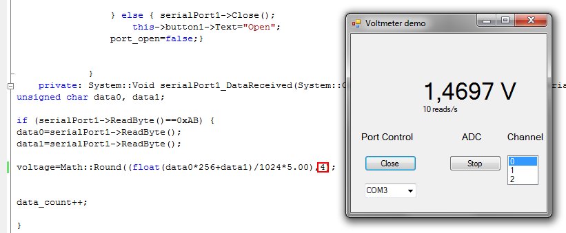
you use 2 pair of byte for read the max value in C++ of "99,99" but if i want to have a higher precision (for example a voltage with 4 numbers after the coma "99,9999") what i need to change?
Real higher precision can be achieved only is ADC have higher resolution. With 10 bit ADC there is 1024(2^10) steps, so if ADC reference(max value that can be measured) is 5 V, then measurement resolution is ~ 0.005 V.
But for show you could have 4 numbers after coma.
Find this line in Form1.h
voltage=Math::Round((float(data0*256+data1)/1024*5.00),2);
replace to voltage=Math::Round((float(data0*256+data1)/1024*5.00),4);
voltage now would be rounded to 4 numbers after coma instead of 2.
QUESTIONS
you use 2 pair of byte for read the max value in C++ of "99,99" but if i want to have a higher precision (for example a voltage with 4 numbers after the coma "99,9999") what i need to change?
Real higher precision can be achieved only is ADC have higher resolution. With 10 bit ADC there is 1024(2^10) steps, so if ADC reference(max value that can be measured) is 5 V, then measurement resolution is ~ 0.005 V.
But for show you could have 4 numbers after coma.
Find this line in Form1.h
voltage=Math::Round((float(data0*256+data1)/1024*5.00),2);
replace to voltage=Math::Round((float(data0*256+data1)/1024*5.00),4);
voltage now would be rounded to 4 numbers after coma instead of 2.
Hiç yorum yok:
Yorum Gönder