A. C. MettingVanRijn, A. Peper, C. A. Grimbergen..
Academic Medical Center, Medical Physics Department, Meibergdreef 15 1105 AZ Amsterdam, The Netherlands, e-mail : metting@biosemi.com
- Abstract - Galvanic isolation of a patient during a bioelectric recording is necessary to ensure the safety of the patient. In a typical measurement situation high interference voltages may be present across the isolation barrier. In this study the necessity of a very high isolation mode rejection ratio - the ability of the amplifier to suppress feed-through from voltages across the isolation barrier to the output - is argued and a design of a multichannel amplifier with an isolation mode rejection ratio of 160 dB is described.
I. INTRODUCTION
The safety regulations in medical care prescribe maximum leakage currents in case a patient should touch ground or mains power during a bioelectric recording [1]. Although the regulations vary between different countries, a sufficient galvanic isolation and an isolation capacitance less than 800 pF are usually demanded (maximum leakage current is 50 microArms when the patient touches the line voltage of 220 Vrms, 50 Hz). An isolation capacitance of less than 300 pF will ensure that the connection of a recording device will not significantly alter the situation of the patient, the normal body capacitance to ground also being in this order [2].
II. ORIGIN OF ISOLATION MODE VOLTAGE
A typical measurement situation with all relevant capacitances is shown in Fig. 1 (switch opened). The capacitance be- tween the body and mains power (Cbody) causes a current ipow to flow through the body to ground. Part of this current (iamp) flows through the neutral electrode (Zrl, the right leg electrode in ECG recordings) to the isolated common of the amplifier and via the isolation capacitance (Ziso) to ground. Consequently, a voltage across the isolation barrier will exist: the isolation mode voltage (vim) [3]. In every isolation amplifier, a certain portion of the isolation mode voltage is fed-through to the output. The ability of an amplifier to suppress feed-through of isolation mode voltages is quantified in the isolation mode rejection ratio [4] :
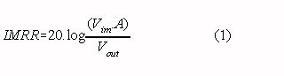
Where : Vim is the isolation mode voltage vout is the amplifier output signal due to feed-through of vim A is the overall gain of the amplifier
In this study two ways of preventing an interference output signal resulting from isolation mode voltages are described. One approach is to reduce the actual voltage across the isolation capacitance with an additional circuit. A better approach, dealt with in section IV, is to design the amplifier in such a way that the feed-through of high isolation mode voltages remains negligible.III. REDUCTION OF ISOLATION MODE VOLTAGE
The magnitude of the isolation mode voltage is proportional to the interference current through the isolation barrier. The current through the isolation barrier (iiso) can be made much smaller than the current from the patient to the isolated amplifier common (iamp) with the circuit pictured in the inlay of Fig 1. (switch closed) [5] :
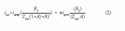
where: A is the open loop gain of the operational amplifier (typically 104 to 105 at 50 Hz)
Large resistors R1 and R2 limit the maximum leakage current through the patient (for example: resistors larger than 40 M for a maximum leakage current of 50 microArms). The main drawback of the circuit is that the amount of interference current (iamp) which can be handled in normal operation is limited to imax = vmax/R1 (vmax is the maximum output swing of the operational amplifier). Consequently, the chosen value of R1 is a compromise between safety on the one hand and isolation mode voltage reduction and current handling capability on the other. Some improvement can be achieved by increasing the output voltage swing of the amplifier, for instance by adding an extra transistor output stage with a high supply voltage [6], [7]. In cases were safety regulations are not very severe, the circuit can be valuable because it is easily added to a system with an insufficient isolation mode rejection ratio while the improvement can be substantial. For example
: when Cpow is 3 pF (ipow is 200 nArms) and a Cbody and Ciso both 300 pF, the circuit (with R1 = 10 M and a typical operational amplifier) reduces the isolation mode voltage from approx. 3 Vp-p to 0.3 mVp-p. Note that with R1 larger than 50 M the circuit would not have been able to function in the typical measurement situation just mentioned.
IV. IMPROVEMENT OF THE ISOLATION MODE REJECTION RATIO
A preferable way to reduce the influence of isolation mode voltage is to increase the isolation mode rejection ratio of the amplifier. High isolation mode voltages are present in a situation where Cpow is large (the patient is situated near power lines), Cbody is small (no big grounded objects near the patient) and Ciso is small. For example: Cpow is 30 pF and Cbody and Ciso both 100 pF leads to an isolation mode voltage of 100 Vp-p. The resulting interference signal should be lower than the amplifier noise level. The equivalent input noise of a typical biomedical amplifier is in the order of 3 microVp-p (approx. 0.5 microVrms) in a bandwidth 0.1 - 500 Hz. Consequently, an isolation mode rejection ratio of 150 dB (at 50 Hz) is required (see Eq. 1.). Commercially available isolation amplifiers (with unity gain) provide an isolation mode rejection ratio of approx. 100 dB at 50 Hz. It follows from Eq. 1 that the isolation mode rejection ratio can be increased with a preamplifier : overall IMRR = IMRR of iso amp + gain of preamp (in dB)
The magnitude of the input signals defines the maximum gain of the preamplifier. With ECG measurements - the required input range being approx. 5 mVp-p - the maximum gain is approx. 60 dB and an isolation mode rejection ratio of 160 dB seems obtainable. Note that a DC rejection circuit is essential to prevent saturation of a high-gain amplifier because the differences in electrode offset voltages produce a DC input signal of several tens of millivolts typically. If the isolation mode rejection ratio is sufficiently high, the isolation mode voltage can still be the cause of inter-ference as differences in electrode-skin impedances and/or stray capacitan- ces convert the isolation mode voltage to a differential amplifier input voltage (vab in Fig. 1) :
The magnitude of the input signals defines the maximum gain of the preamplifier. With ECG measurements - the required input range being approx. 5 mVp-p - the maximum gain is approx. 60 dB and an isolation mode rejection ratio of 160 dB seems obtainable. Note that a DC rejection circuit is essential to prevent saturation of a high-gain amplifier because the differences in electrode offset voltages produce a DC input signal of several tens of millivolts typically. If the isolation mode rejection ratio is sufficiently high, the isolation mode voltage can still be the cause of inter-ference as differences in electrode-skin impedances and/or stray capacitan- ces convert the isolation mode voltage to a differential amplifier input voltage (vab in Fig. 1) :
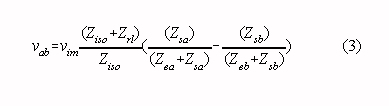
where: Ziso is the impedance of the isolation capacitance Zrl is the electrode-skin impedance of the neutral electrode Zea, Zeb are electrode-skin impedances of the measuring electrodes Zsa, Zsb are impedances of stray capacitances
It is instructive to rewrite this equation assuming that Ziso is much larger than Zrl, and that the impedances of the stray capacitances are much larger than the electrodes-skin impedances :
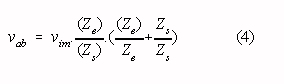
where: Ze = « (Zea + Zeb); Zs = « (Zsa + Zsb) Ze = Zeb - Zea ; Zs = Zsa - Zsb
The influence of the isolation mode voltage appears to be depending on the stray impedances and their relative differences and on the (with every recording different) electrode-skin impedances. Now consider a relative difference in electrode-skin impedances of 50 % and a mean electrode-skin impedance of 100 k at 50 Hz (a "bad", but not unusual measurement situation). It follows from Eq. 4 that with equal stray capacitances as small as 0.1 pF - a typical value for the capacitance between unshielded input wires and ground - the isolation mode voltage will produce an input interference voltage of vab = = (1.5 x 10-6.vim), which is equivalent to an (insufficient) isolation mode rejection ratio of 116 dB. However, even with the use of shielded input wires, small stray capacitances are easily introduced if the input stage and the grounded output stage are located in the same cabinet. It follows from Eq. 4 that with the aforementioned electrode impedances equal stray capacitances smaller than 0.002 pF are required to reduce interference to a level equivalent with an isolation mode rejection ratio of 150 dB.
V. DESIGN OF AN 8-CHANNEL ECG AMPLIFIER
We developed an 8-channel ECG amplifier with an isolated low-noise input section and eight separate analog output signals. A circuit diagram (one channel) is given in Fig. 2 and the specifications are listed in Table I.
Isolation is accomplished with optically coupled isolation amplifiers (Burr-Brown 3650) offering an isolation mode rejec- tion of 100 dB at 50 Hz (with unity gain). Power supply of the isolated section is by two maintenance free lead-acid batteries (12 V, 2.6 Ah each; maximum continuous operation time is approx. 10 hours). A two stage preamplifier based on low-noise FET operational amplifiers (OPA 2111) precedes the isolation amplifier. FET operational amplifiers are used because of their low current noise, resulting in lower noise than achievable with bipolar operational amplifiers in measurements with source resistances higher than approx. 30 k . One of the applications of the amplifier is the recording of His-bundle activity at the body surface [8], [9]. A major portion of these recordings is to be performed with neonatals, where we noted relatively high electrode-skin impedances (mean value approx. 100 k ). The low-frequency common mode rejection ratio is made in- dependent of imbalances between the two high-pass filters (required for DC suppression) by connecting the resistors of the filters to a low-impedance version of the common mode signal (personal communication, A. P. Kuiper). A guarding circuit [10] ensures a high common mode input impedance with shielded input leads and a driven right leg circuit [11] reduces the common mode voltage by 50 dB at 50 Hz. Overall gain of the amplifier circuit is 60 dB and an isolation mode rejection ratio of 160 dB was readily achieved with balanced source impedances. However, proper design of the cabinet proved to be essential to prevent interference with unbalanced source impedances. The input leads of the operational amplifiers in the first amplifier stage are mounted directly to the input connectors and the complete input section is shielded with the shield connected to the isolated common. These construction details, combined with guarded input wires, ensure minimum stray capacitances between the amplifier inputs and ground. As a result, the interference level with a mean source impedance of 100 k and a relative difference in source impedances of 50% was equivalent to an isolation mode rejection ratio of 160 dB.
| Table I: Amplifier specifications | |
| Equivalent input noise voltage (µVrms, 0.1-500 Hz): | 0.5 |
| Equivalent input noise current (pArms, 0.1-500 Hz): | 0.03 |
| Bandwidth (+0, -3 dB) (Hz): | 0.16-500 |
| Differential mode DC input range (mV): | 1000 |
| Differential mode AC input range (mVp-p): | 20 |
| Common mode input range (Vp-p): | 10 |
| Input bias current (nA per input): | 0.01 |
| Gain: | 1000 |
| Common mode input impedance (MOhm at 50 Hz): | 200 |
| Differential mode input impedance 1 (MOhm at 50 Hz): | 15 |
| Common mode rejection ratio (dB at 50 Hz): | 120 |
| Isolation mode rejection ratio 2 (dB at 50 Hz): | 160 |
| Maximum leakage current (µArms): | 20 |
| Power consumption (W, eight channels) | 2.8 |
VI. DISCUSSION
It was shown in this paper that an 8-channel isolation amplif- ier with a very good isolation mode rejection ratio can be built with commercially available components, provided that special attention is paid to the shielding of the amplifier inputs. If a system with many more than eight channels is built, the total isolation capacitance of the parallel isolation amplifiers may become unacceptably large. The number of isolation amplifiers can be reduced by multiplexing, i.e. several channels are handled by a common isolation amplifier. The most promising technique for a multi-channel (> 20) measu- rement system is the digital transfer of information. A system with a multiplexer and A/D converter and with serial data transmission through an optical fiber can offer minimum isolation capacitance (the distance between isolated and grounded sections can be large), minimum stray capacitances from amplifier inputs to the grounded section (the isolated section and grounded section can be in different shielded cabinets) and maximum isolation mode rejection (only extremely large interference signals can corrupt the digital information). The main problem of such an optically coupled system is the power supply of the isolated section as the addition of a DC-DC converter would jeopardize the favorable points just men- tioned. Fortunately, power supply with small-sized batteries becomes more and more a realistic alternative with modern low-power components (a multichannel amplifier, multiplexer, A/D converter and optical transmitter with a combined power consumption less than 100 mW are needed). It was shown by our group that multichannel low-power biomedical amplifiers with very good specifications can be constructed [12]. Low-power CMOS A/D converters and multiplexers became commercially available over the last years. However, the relatively large power consumption of the optical transmitters (LED or LASER) remains a problem.Acknowledgement
This research was supported by the Technology Foundation (STW).
References
[1] W. H. Olson, "Electrical safety," in Medical instrumenta- tion: application and design (editor: J. G. Webster). Boston: Houghton Mifflin Co., 1978, pp. 667-706.
[2] J. C. Huhta and J. G. Webster, "60-Hz interference in electro-cardiography," IEEE Trans. Biomed. Eng., vol BME-20, no. 2, pp. 91-101, 1973.
[3] R. Pallas-Areny, "Interference-rejection characteristics of biopotential amplifiers: a comparative analysis," IEEE Trans. Biomed. Eng., vol. BME-35, no. 11, pp. 953-959, 1988.
[4] M. F. Zirmgast, "Capacitive isolation expands analogue design options - Part 1 and 2," Electronic Engineering, April, pp. 37-40 and May, pp. 33-45, 1989.
[5] I. C. Forster, "Measurement of the body capacitance and a method of patient isolation in mains environments," Med. & Biol. Eng., vol. 12, pp. 730-732, 1974.
[6] J. G. Graeme, Applications of operational amplifiers. New York: McGraw-Hill, 1973, pp. 46-48.
[7] J. G. Graeme, Designing with operational amplifiers: application alternatives. New York: McGraw-Hill, 1977, pp. 12-14.
[8] A. Peper, R, Jonges, T. G. Losekoot, and C. A. Grimbergen, "Recording of surface His-Purkinje potentials," Med. & Biol. Eng. & Comp., vol. 23, pp. 365-376, 1985.
[9] A. Peper, The recording of His-Purkinje potentials at the body surface. Ph. D. thesis, University of Amsterdam, 1990.
[10] A. C. Metting van Rijn, A. Peper and C. A. Grimbergen, "High quality recording of bioelectric events. I: inter- ference reduction, theory and practice," Med. & Biol. Eng. & Comput., vol. 28, pp. 389-397, 1990.
[11] B. B. Winter and J. G. Webster, "Driven-right-leg circuit design," IEEE Trans. Biomed. Eng., vol. BME-30, no. 1, pp. 62-66, 1983.
[12] A. C. Metting van Rijn, A. Peper and C. A. Grimbergen, "High quality recording of bioelectric events. II: a low-noise low-power multichannel amplifier design," Med. & Biol. Eng. & Comput., in press
Hiç yorum yok:
Yorum Gönder